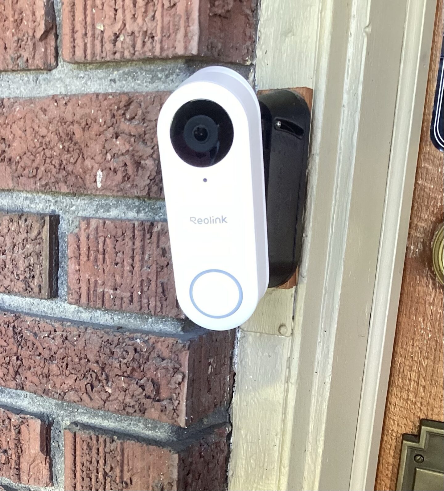
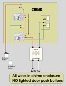
Reolink v2 WiFi Hardwired with Mechanical Chime- How to install Reolink WiFi doorbell with mechanical chime
Can a Reolink WiFi doorbell camera with a 915MHz frequency (V2) be wired to a wired chime?
Yes it can!!
Available Options that Won’t Work!
These are just some cliff notes of things that have been discussed by others and I pursued as options but here is why they are dead ends and don’t work! Please feel free to skip this section over if you are not interested in the nitty gritty!!!
- Axxess Wireless Chime Relay $116 (sold to commercial end users) is a solid state relay that allows wireless remote control of a powered chime with real chime bars. HOWEVER while reading through the installation instructions it says that the relay needs to be paired with their proprietary wireless doorbell buttons.
- LR20IL Lora Relay 30A 915MHz MHz frequencies: 433M/ 868M/ 915M- dead end?
- Because the Reolink V2 WiFi doorbell uses a smart 915MHz protocol rather than voltage drops on a traditional circuit to trigger its chime, you must use your smart home system to detect the Reolink press and transmit a signal via LoRa to the LR20IL.
- ZEN58 Low Voltage XS Relay as a Smart Doorbell-Z wave Relay ONLY WORKS WITH NON SMART NON LIGHT POWERED DOORBELLS!
Options that will work
In no particular order lets jump in..
- V2 chime + relay modification
- Does not have inching mode = software programming needed to control switch timer.
- WiFi relay module 2.4ghz (MHCozy) – routes through cloud servers +app
- Zigbee 433mhz relay (Mhcozy) – offers local networking no cloud delay
- ⚠️ Zigbee and zwave require compatible hubs like smart things and home assistant.
- The MHCOZY device doesn’t require any re-flashing (software programming) to work as a relay powered by the 16V 30VA doorbell transformer. The default mode for the NO (normally open) relay is a momentary switch with a 1 second on. This means no need to have to program any on-off delay logic to mimic a typical doorbell press
- Solid state relay soldered
- This was my first choice until I lost the part I needed and the motivation!
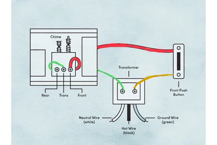
Wiring Diagram for Regular Doorbell
Power Bypass
My personal choice was to take the path of least resistance! So I chose to install the Mhcozy zigbee relay switch!
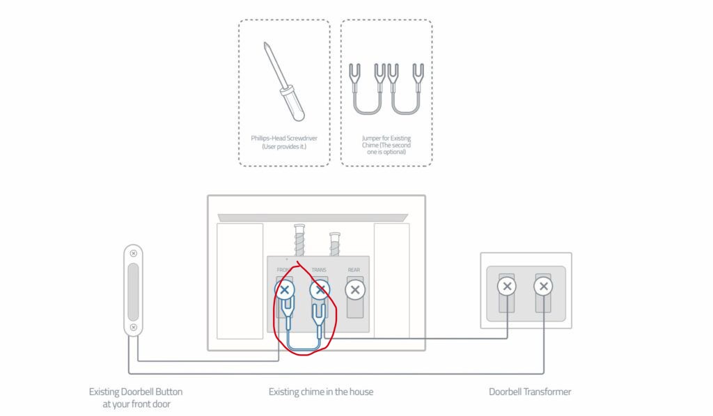
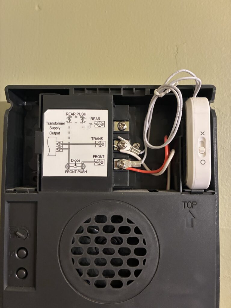
When doing a lateral change from a competitors smart doorbell to the reolink The very first step is to remove the power bypass bridge/jumper cable aka power kit. Companies like Arlo and Ring provide these free so if you are changing over from a different doorbell camera double check for an electric bridge bypass and remove it.
Wiring Diagram for Inline Relay powered by Transformer.
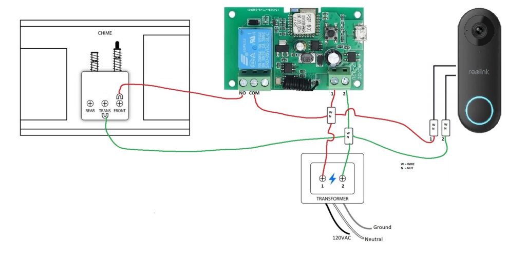
Technowizard’s diagram shows the use of wire nuts, it is a very nice and clean looking install but it confused me because I need to see things from a more color coded perspective.
Relay module Zigbee or WiFi
Whatever relay switch you buy make sure it has inching mode aka momentary/jogging mode. This will allow the device to be set to auto turn off like a normal button.
This is going to be the easiest install method that does not require implementing code to integrate into your smart home network.
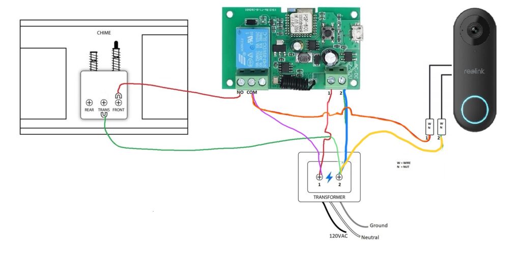
I connected my wires directly to the transformer: the Orange and Fuchsia wires both connect into the COM terminal and provide the extra power the Reolink doorbell needs, since the electrical bypass was removed/not installed inside the chime box. The green wire is the original transformer wire run from the doorbell chime that got to stay in place. One of the original wires already goes from the transformer to the doorbell to power it (yellow), and another two wires are installed to go separately from each individual transformer terminals to the zigbee relay terminals #1 and #2 (#1 red, #2 blue) to power it.
Programming
So I installed the zigbee relay using my Smart Things hub. So step #1. Activate pairing mode. You push and hold the pairing button until it turns a blue light, roughly 8 seconds, and then it will begin to flash red to indicate it is in pairing mode.
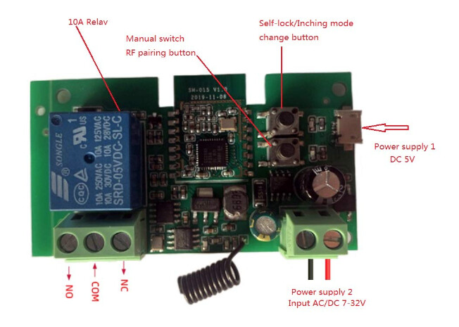
The zigbee comes default set to inching mode timed at 1 second. I had to manually push the mode change button to get out of 1 second inching mode and go into solid state mode, where the power remains on until it is turned off.
Next I went into the Smart Things app and created a routine IFTTT saying that if the doorbell is powered on then turn it off after 7 seconds. This is the exact amount of time that my electric chime needs to activate a full cycle.
If using the WiFi relay then you will want to look in the Tuya or eweLink app under the device settings icon to change your inching mode time, if you need to do that. This settings icon is not available in the ST app so I had to find a work around by making a routine in solid state mode.
POE Install Diagram
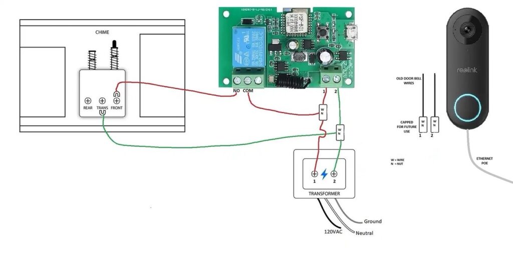
Power Over Ethernet = electricity to power the doorbell. This means you can cap off those low voltage wires.
Final Touches
At this point I decided I should probably keep the doorbell and ordered my memory card. It arrived a day later and I flashed it and installed it.. it took a few tries before reolink accepted it. And rebooted.
0-20 degree angle mount… Thankfully the size of the reolink is nearly identical to my Arlo Doorbell camera which means I can reuse my existing mounting wedge Wasserstein with minimal modification.
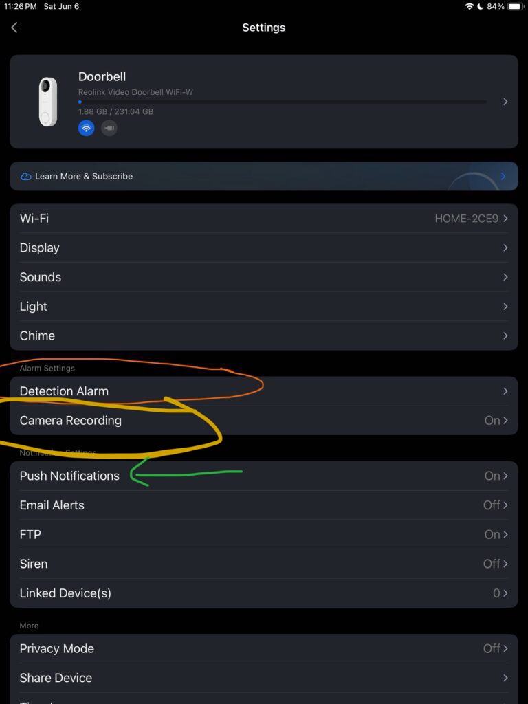
Reolink Recording Settings
It is worth mentioning that in no particular order;
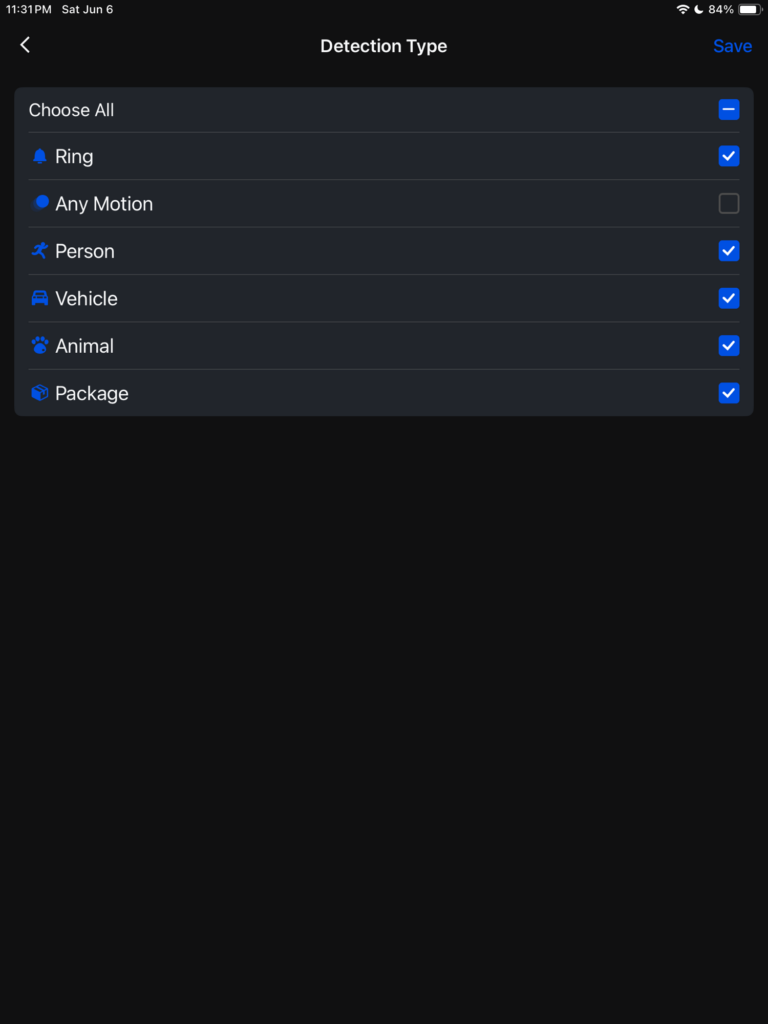
#1. Turn off “any motion” recording to prevent artifact recording aka garbage tree moving and bugs flying.
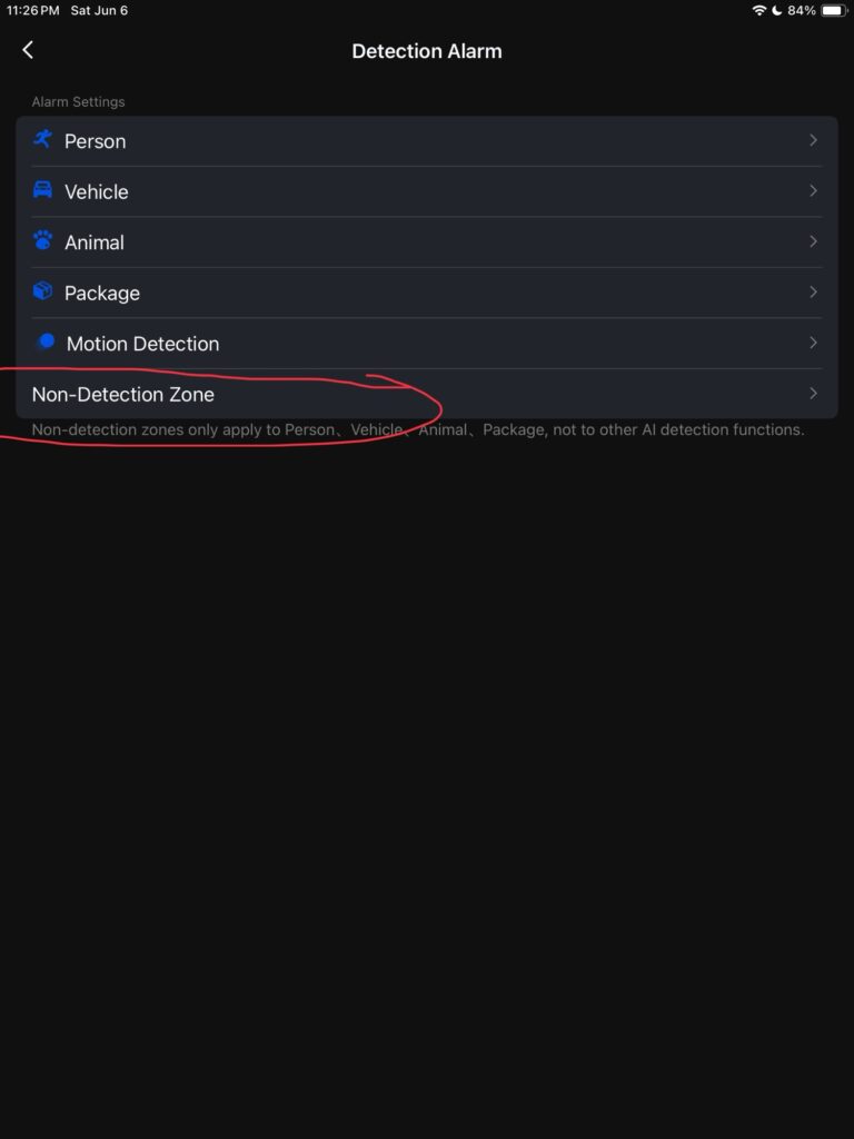
#2. Set the non detection-zones as this allows for areas such as streets, bushes, and trees to be tagged as non trigger areas within the field of view of the camera.
#3. Customize notifications.
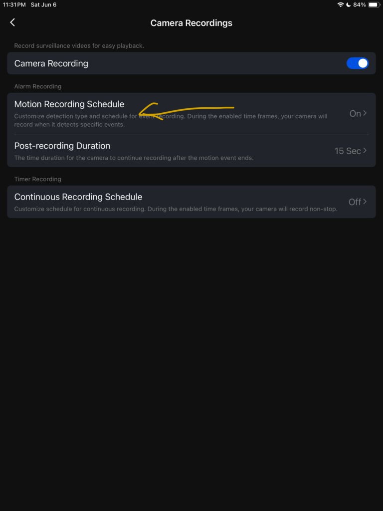
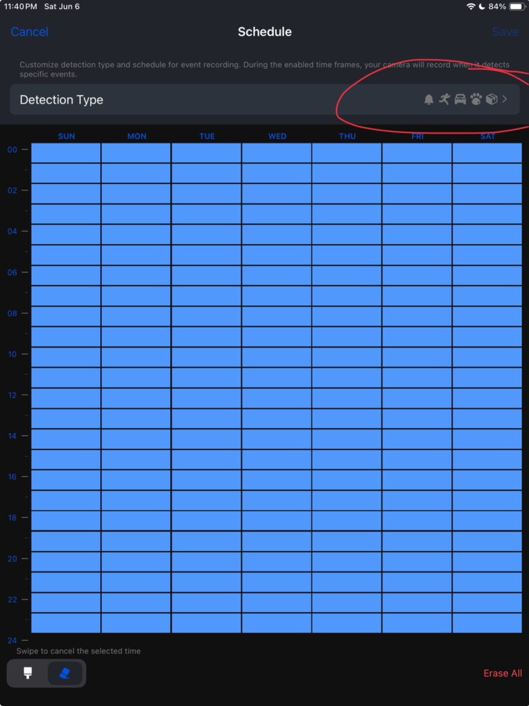
Motion Recording Schedule allows you to deselect what events will trigger the camera to record video. This is where you can deselect “any motion”.
You can also turn off the LED button light and the chime that sounds at the doorbell.