80 series Automotive Auxiliary Power Part #2
By this point we know what we want to power, how much power we need to run, the gauge and length of our electrical wire, and even the lug and terminal connecting rings.
I want power ports in the main cabin and the rear quarter panel of the vehicle. for this I will install two separate fuse blocks.
Note: Honestly after completing installation it dawned on me that I could have saved a lot of money and run power straight through my 30amp relay and not installed the fuse block in the front.
Grounding the Auxiliary Battery
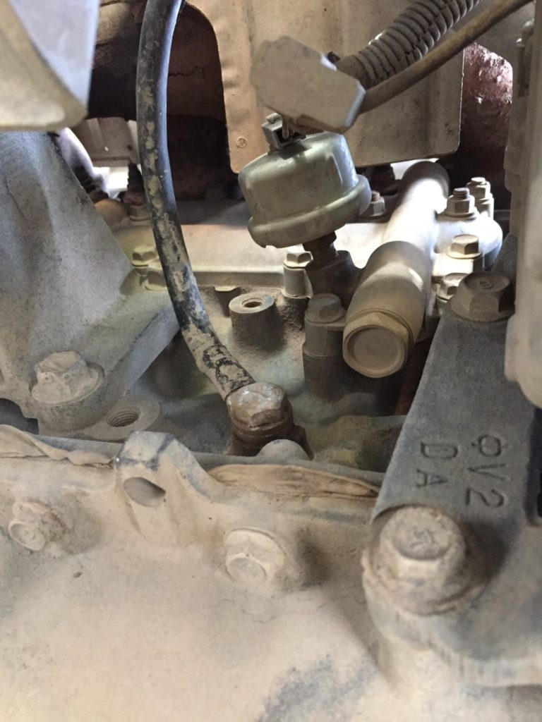
Ih8mud gave me a great mounting location for my 2 gauge grounding cable. Using an M10 1.25x20mm fine pitch bolt and two washers to bolt into the engine block. There is an unused threaded bolt hole on the engine block next to the oil pressure sender. Be warned that this bolt hole is going to require cleaning with a wire brush before the M10 bolt will thread into place.
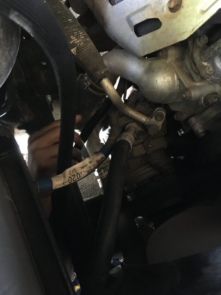
The next grounding cable is installed from the auxiliary battery negative to the chassis.
Additional Supplies
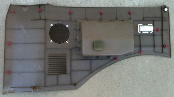
Before you do anything take inventory and order interior trim retention clips. I took apart my rear quarter panel before ordering any electrical supplies and many of my clips were broken and missing. It is highly likely that the clips holding the automotive interior trim in place May break when removing the pieces to run the electrical cable.
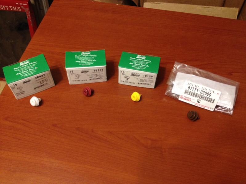
- White clips Part #90467-09206
- Brown clips part #67771-32060
- Yellow clips part #67771-30090
- Red clips part #67771-12050, 67771-28020
ClipsandFasteners.com
- Yellow A19129
- Red – A19257
- White – A20437
Removing the Front Passenger Seat
If you have reached this point and have decided that your power needs include the installation of the 6 slot Blue Sea fuse block then the passenger seat will need to be removed.
#1. Remove the 4 bolts, 2 in the front and 2 accessible from the back seat floorboard.
#2. Have a piece of wood or a second person to pry or tilt the seat backwards into the back seat cabin area. This will expose all of the underneath electrical wiring of the seat.
#3. Take pictures of the existing wiring.
#4. Cut away the zip tie holding the electrical wiring to the bottom of the seat frame.
#5. Disconnect the electrical connections. For me this was five connectors including the heated seats.
Installation of Junction Block, Fuse Block, Relay, Switches & More.
None of my installation involved soldering connections.
#1. Install electrical wire before making cuts, crimps, and heat shrink or soldering connections. This helps with making accurate cut lengths.
#2. After the electrical wire is installed then attach the terminal rings, butt connectors, and female pin connectors.
#3. After crimping all connections use the heat gun with heat shrink or electrical tape to seal all connections where water or excess moisture might come in contact with the cable.
#.4 Leave enough slack on the electrical wire so that the wires can easily be fed through the trim pieces to the accessory connectors when re installing them with the trim.

Step by Step
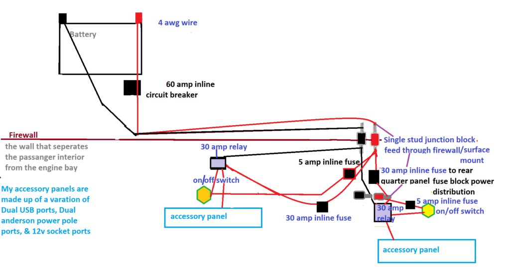
#1. We start at the battery, the 4 awg cable will be attached to the positive and negative terminals.
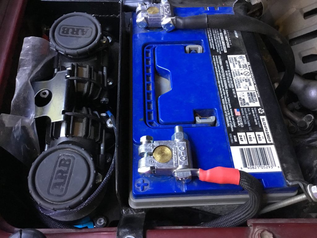
NOTE: Before completion the battery negative needs to be ground to a portion of the Engine Block and chassis and preferably coated with dielectric grease to prevent corrosion.
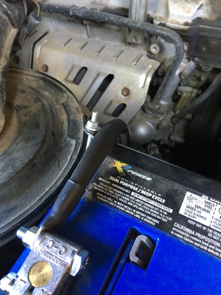
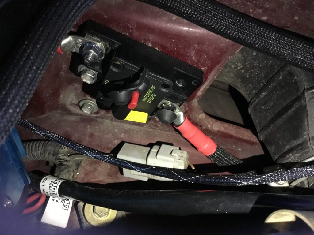
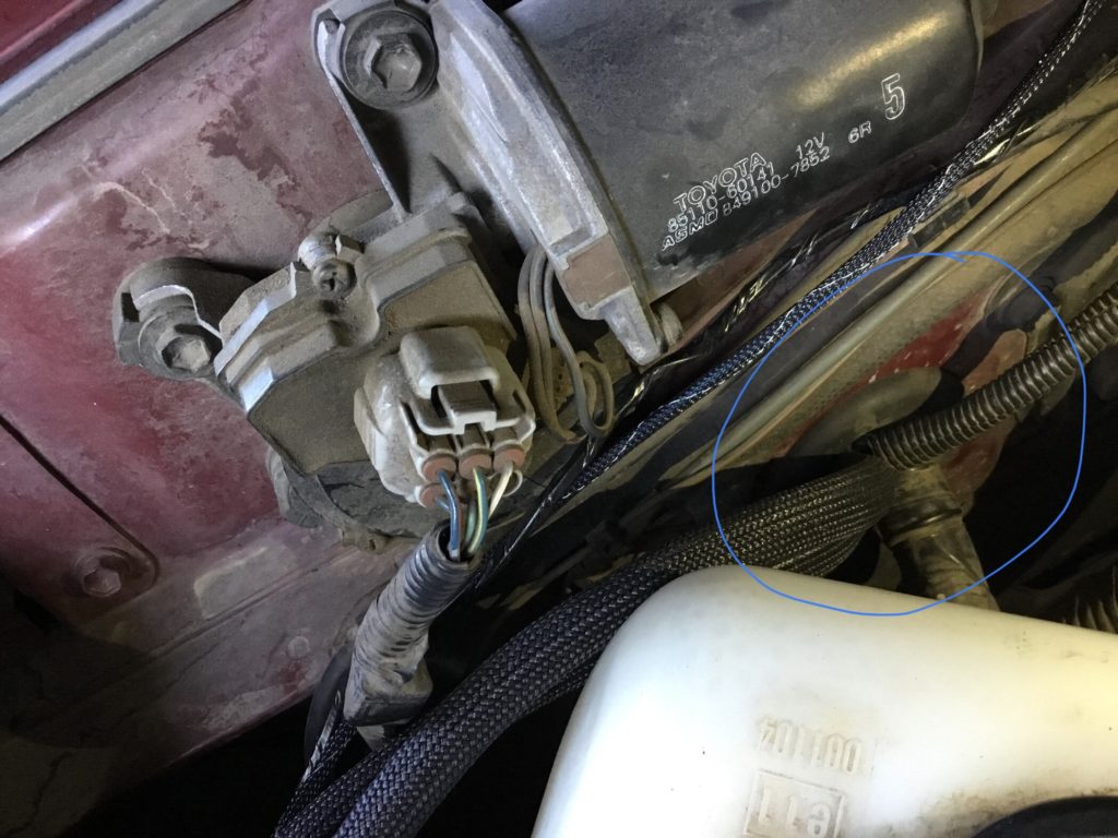
#2. Next install, Closest to the battery, an inline circuit breaker.
For example I am running 60 amps of power so I will install a 60 amp circuit breaker. This is necessary to protect the battery from any power surges.
#3. Using the electrical snake wire guide find a port of entry through the firewall and boot to pull the wires through and into the main cabin area. my battery is installed on the passenger side so I ran my 4 awg through the passenger firewall. My air compressor cables were run through the driver side firewall.
#4. From the circuit breaker the power and parallel ground wire runs to a junction block.
I chose to install a surface mount single stud block for the negative and positive cables. I found a location underneath the front console that covers the shifter.
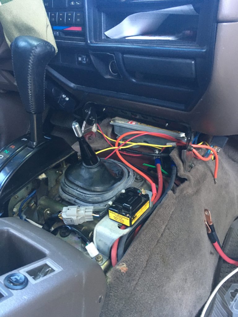
The junction block serves as a power station hub. Think of it as a train station. The power and ground cables come in and then diverts to different sections from this point. If the Ground stud is not connected to the battery ground then ground it to an unpainted portion of the chassis!
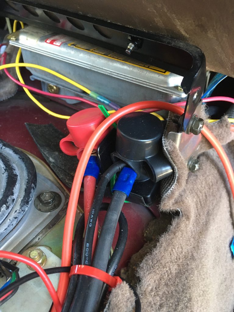
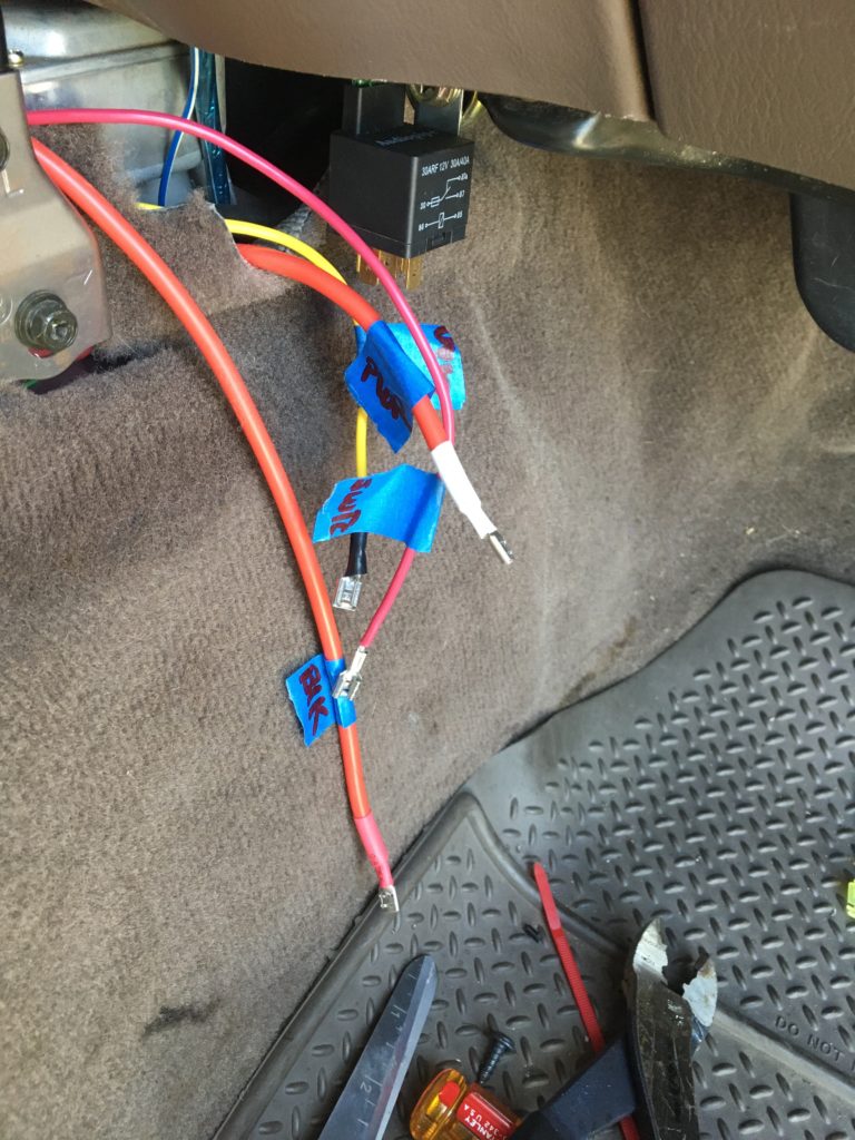
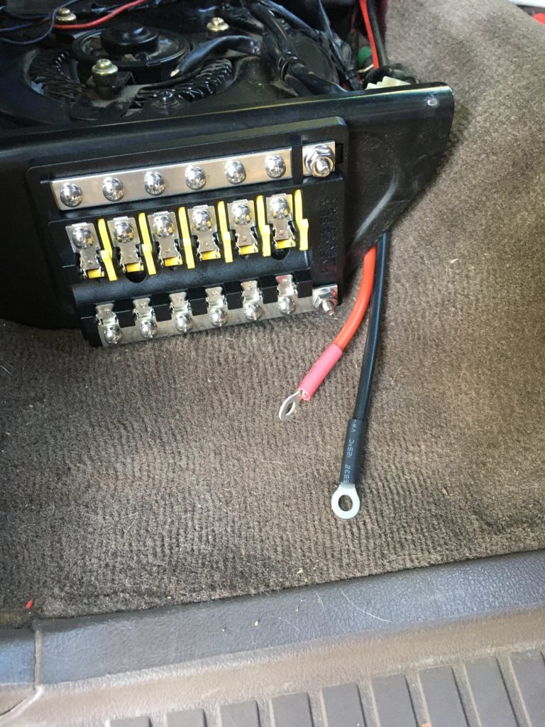
#5. It was at this point that I ran into as light problem. The metal box seen in the picture above presented an obstacle for the normal electrical pin disconnect terminal lugs. I ended up buying 90 degree right angle terminal disconnect female lugs and this resolved the issue and everything slid and bolted back into place.
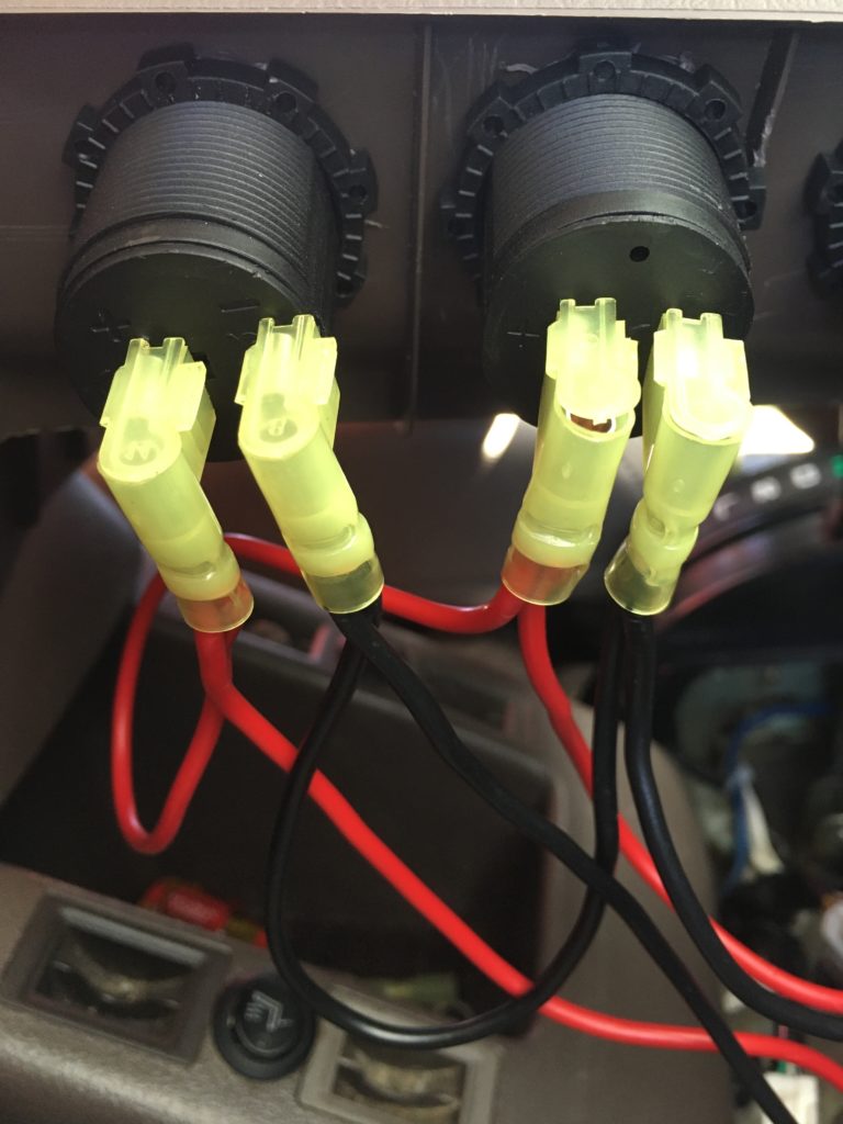
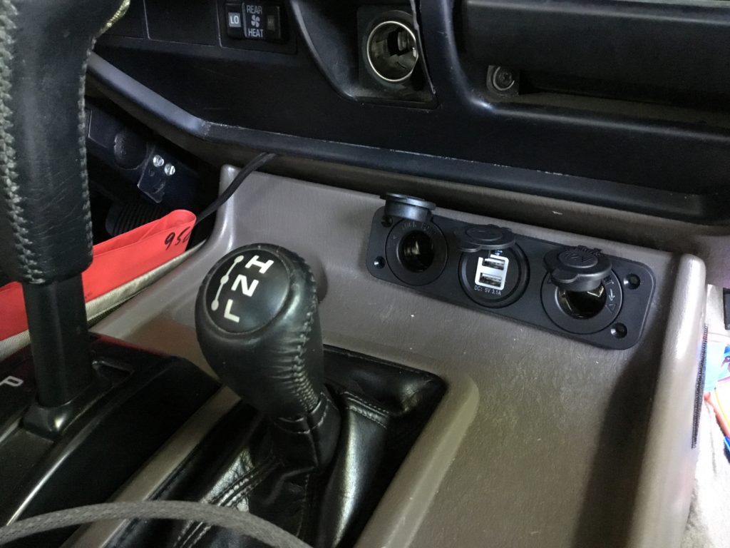
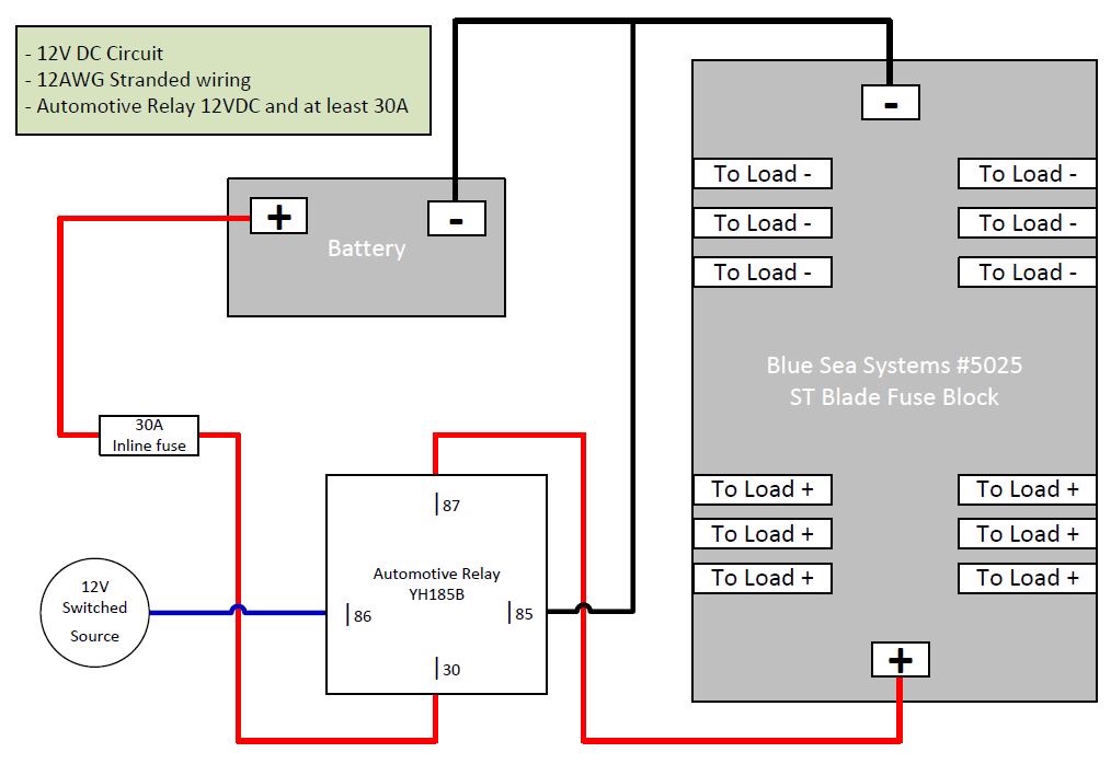
#6. From the junction block power and ground runs to a toggle switch and a 30 amp relay. From the relay the power and ground runs to the Blue Sea Fuse Block On the passenger seat. From the fuse Block power and ground are run to the accessory power ports.
Back at the junction block, power and ground are run on a new separate 6 gauge line to a second junction block in the rear quarter panel And then to the blue sea fuse block.
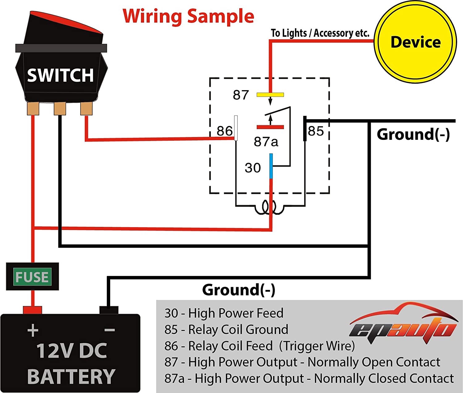
Power Relays
Power relays or solenoids? For my install I chose to use relays because of their size and ease of install. It is worth noting that there is a significant voltage drop aka loss of power when using a solenoid.
This detailed explanation of how relays operate really helped me understand their importance and functionality.
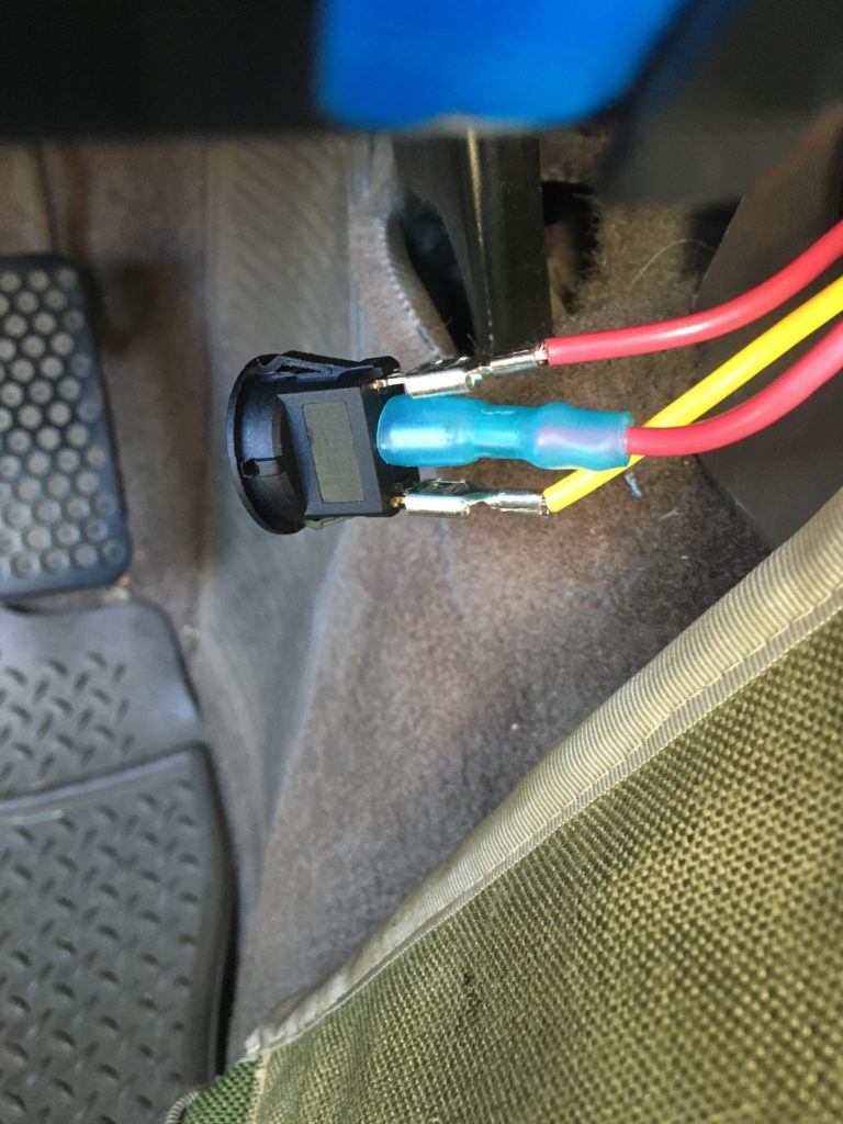
I also chose to use a toggle switch to control the front and rear power blocks independently.